The nonlinearities such as hysteresis and creep are the major factors inherent in PZT actuation that affect the tip positioning precision and manipulation performance of the AFM system. Hysteresis causes a multi-valued mapping between excitation voltage signal and displacement of PZT. Creep effect occurs when a driving voltage signal of PZT stands still, as the displacement of PZT keeps changing slowly and cannot be hold at a certain value. Several modified PI model were proposed for compensation of both creep and hysteresis, in which the creep effects are described as a first order linear system. With these methods for hysteresis and creep compensation, the creep effects are considered for all the time during the whole PZT activation process and depend on the history of excitation voltage signal, which makes the computation of the inverse model difficult.
Researchers from Shenyang Institute of Automation (SIA), Chinese Academy of Science, proposed an extended PI model by introducing an inflexion creep model into the hysteresis operator to compensate for creep effects only at the turning points of the single hysteretic loop, which significantly improves the tip positioning precision. The extended PI model is then generalized with consideration of multi-loop hysteresis, for which the inflexion creeps are modeled as a generalized function of time with magnitude depending on the values of the corresponding turning points of the driving voltage signal. Therefore the complete extended PI model can be used to compensate for the inflexion creeps at any turning point on the hysteretic loops. Furthermore, the number of parameters in the creep model has been greatly reduced into three, which mathematically reveal the relationship between the creep effect and the driving voltage in PZT actuation.
The proposed inflexion function and the basic operator of the extended Prandtl-Ishlinskii (PI) model are as follows:
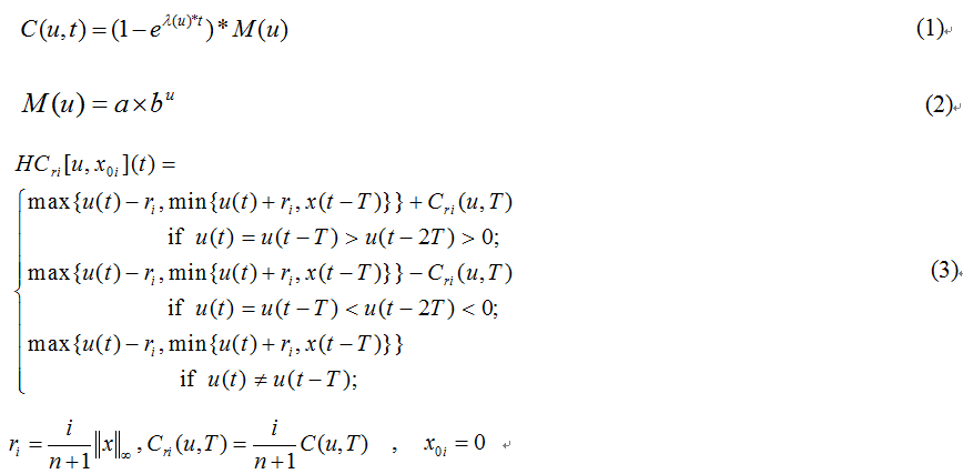
where, Eq.1-2 are the inflexion function and Eq.3 the basic operator of the extended PI model as considering both inflexion creep and hysteresis effect in one basic function.
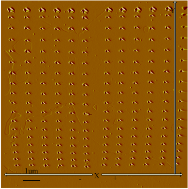
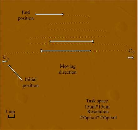
(a) (b)
Fig.1. Illustration of the inflexion creep and the hysteresis character. (a) Inflexion creep calibration experimental results using AFM system. (b) Multi-loop hysteresis calibration results in horizontal direction. (Image provided by WANG Zhiyu et.al)
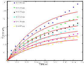
(a) (b)
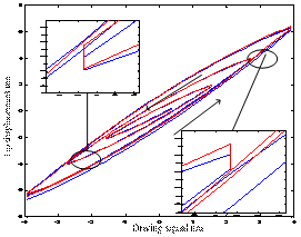
Fig.2. Calibrations for the inflexion creep and the hysteresis character. (a) Curve fitting for the inflexion creep by Eq.1~2. (b) Multi-loop hysteresis curve fitting by Eq.3. (Image provided by WANG Zhiyu et.al)
(a) (b)
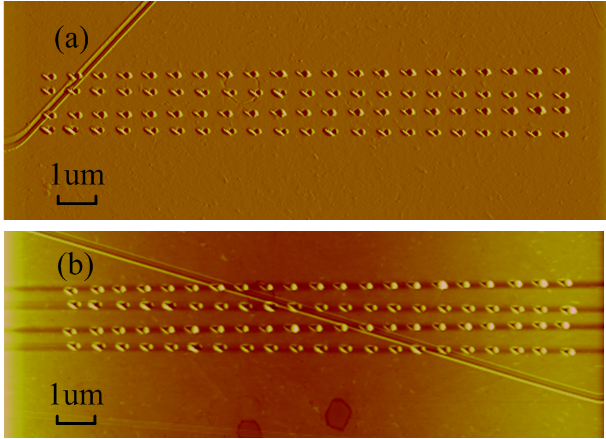
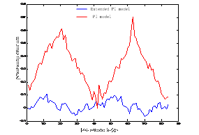
Fig.3. Indentation experiments for AFM tip positioning by the Extended PI model and the PI model. (a) Indentation array comparison between the Extended PI model (upper) and the PI model (lower). (b) Positioning error distribution statistics. (Image provided by WANG Zhiyu et.al)
This work was published on the 2014 IEEE International Conference on Robotics and Automation (ICRA).It was supported by the National Natural Science Foundation of China (Grant No. 61327014, 61304251), and the CAS/SAFEA International Partnership Program for Creative Research Teams.
CONTACT
Wang Zhiyu
Shenyang Institute of Automation, the Chinese Academy of Sciences
Email:zywang@sia.cn